


Compensation and thermoelectric cables
Compensation cables are the link from thermocouple assembly to reference junction. The wires consist of alternative materials, not identical to the individual appendant thermocouples, yet possessing the same thermoelectric properties within the permissible temperature range pursuant to DIN 43722.
Following the law of homogenous circuits, the material between measurement and reference junctions must not vary.
In theory, the thermocouple could lead all the way to the reference junction, which, mainly due to cost reasons, is not practised.
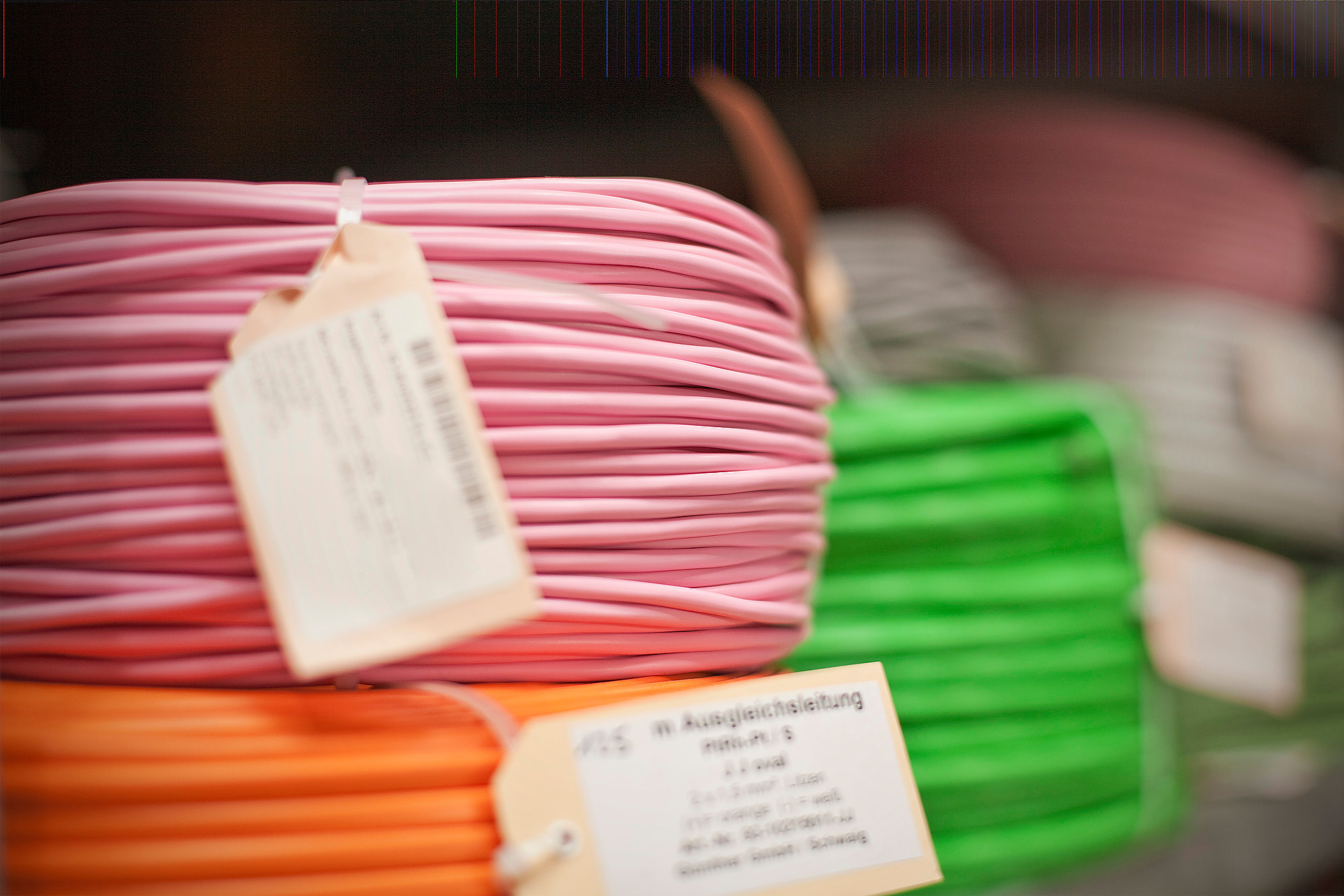
Illus. Compensating cable
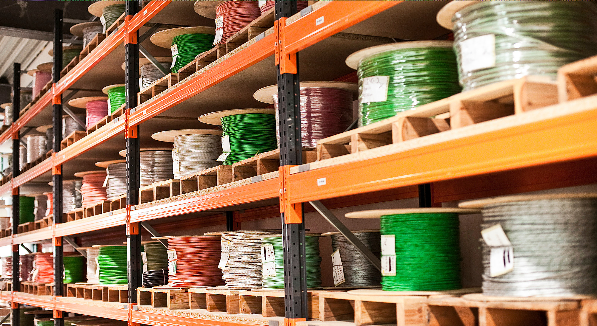
Illus. More than 200 compensating and thermo-line types directly in stock.
Compensation cables have either solid or litz wires and are produced with various strand counts, shielding and insulation.
They are marked with code letter C, which is placed after the code letter for the appendant thermocouple, e.g. SC for a platinum thermocouple type S.
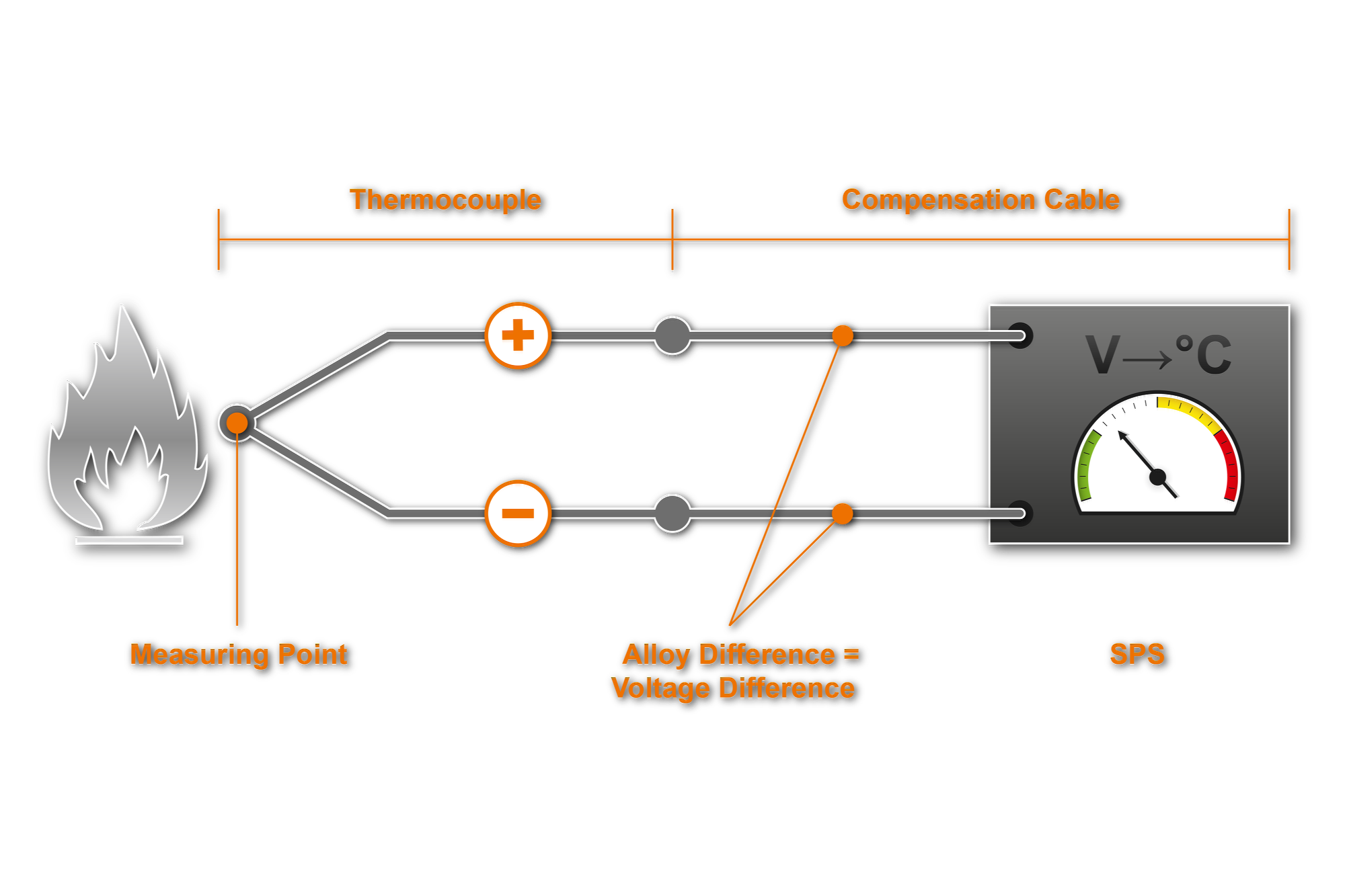
Illus. Installation measure circuit
Thermoelectric cables are made of the same material as the appendant element.
By joining the wire at one end, thermoelectric cables become thermocouples, something that is practiced in drag measurement, for example.
Thermoelectric cables are available as litz or solid wires with various types of insulation. They are marked with the letter “X”, which is placed after the code letter of the thermocouple, e.g. “KX” thermocouple for NiCr-Ni-element, type K.

Coding of Thermoelectric and Compensation Cables
Colour coding of thermoelectric and compensation cables is standardised in DIN EN 60584-3. Standardisation contributes to minimising the danger of confusion and current reversal.
The maximum operating temperature is defined by the insulating material, therefore the corresponding data sheets should be observed.
| Insulating Materials | Max. Temperature |
|---|---|
| PVC | 105°C |
| TPE-0 | 130°C |
| ECTFE | 135°C |
| ETFE | 155°C |
| Silicone | 180°C |
| FEP | 205°C |
| MFA | 235°C |
| PFA | 260°C |
| E-Glass Fiber | 400°C |
| R-Glass Fiber | 700°C |
| Silica | 1000°C |
| Nextel | 1200°C |
III. Temperature resistances for different insulating materials of compensation and thermoelectric cables
Tolerances and Limiting Deviations
Wires for thermoelectric and compensation cables are standardised in DIN 43713. Thermoelectric voltages within the permissible temperature range correspond to the thermoelectric voltages of thermocouples pursuant to DIN EN 60584-1. Tolerances for thermoelectric and compensation cables are defined in DIN 43722.
There are two classes of accuracy:
- The narrower class 1 is for thermoelectric cables only, meaning only those cables with the original materials.
- Class 2 is for thermoelectric and compensation cables made from alternative materials.
GÜNTHER thermoelectric and compensation cables are consistent with the colour coding of DIN 43722, with the exception of thermoelectric cables type U and type L, which are colour coded pursuant to DIN 43714. Tolerances are consistent with accuracy class 2 pursuant to DIN 43722.
For thermocouples type U and type L, the tolerance pursuant to DIN 43719 of ± 3°C applies.
For thermocouple type B, copper wires may be used within a temperature range of up to 100°C. For this reason, DIN 43722 contains no tolerance values for these compensation cables. If compensation cables for type B are required for temperatures above 100°C, the application of specialised compensation cables is necessary. These cables are available upon request.
Choose your language
Leave your number and we’ll call you back
Your direct contact to our team
GÜNTHER GmbH
Temperaturmesstechnik
Bauhofstraße 12
D-90571 Schwaig
info@guenther.eu
Tel. +49 (0)911 / 50 69 95-0
Fax +49 (0)911 / 50 69 95-55